How are patch panels wired?
2026-03-16
Content
- 1 How Patch Panels Are Wired: The Direct Answer
- 2 Understanding the T568A and T568B Wiring Standards
- 3 Tools and Materials You Need Before Starting
- 4 Step-by-Step: How to Wire a Network Patch Panel
- 4.1 Step 1 — Mount the Panel and Plan Your Layout
- 4.2 Step 2 — Route Cables and Leave Adequate Service Loop
- 4.3 Step 3 — Strip the Outer Jacket
- 4.4 Step 4 — Untwist and Seat the Conductors
- 4.5 Step 5 — Punch Down Each Conductor
- 4.6 Step 6 — Apply Strain Relief and Cable Management
- 4.7 Step 7 — Test Every Port
- 5 Patch Panel Types and When to Use Each
- 6 Cat5e vs Cat6 vs Cat6A Patch Panels: Performance Differences
- 7 How Patch Panels Connect to Switches and End Devices
- 8 Common Wiring Mistakes and How to Avoid Them
- 9 Patch Panel Wiring in Real-World Scenarios
- 10 Maintaining and Troubleshooting a Wired Patch Panel
How Patch Panels Are Wired: The Direct Answer
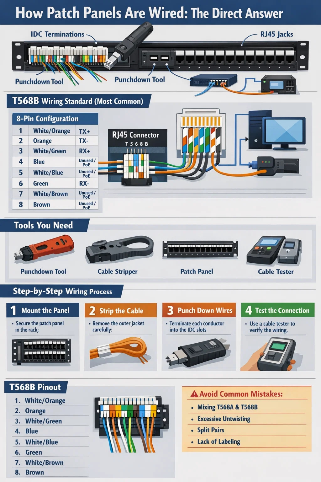
A network patch panel is wired by terminating individual copper conductors from a structured cabling run into the rear of the panel using a punchdown tool, following either the T568A or T568B wiring standard. Each of the eight conductors in a Cat5e, Cat6, or Cat6A cable is seated into a color-coded IDC (Insulation Displacement Connector) slot on the back of the patch panel port. Once punched down, the front of the panel exposes RJ45 keystone jacks, allowing short patch cables to connect equipment to switches, routers, or other network devices.
The entire purpose of a patch panel in a network rack is to act as a fixed, organized termination point for horizontal cable runs, keeping your infrastructure clean and making moves, adds, and changes easy without disturbing the permanent cabling behind the walls. Most professional installations use T568B as the default wiring standard, though T568A is required for government buildings under certain standards. What matters most is consistency — never mix standards across the same run.
Understanding the T568A and T568B Wiring Standards
Before you touch a single wire, you need to understand the two wiring standards used across virtually all structured cabling in the world. Both T568A and T568B use all eight conductors in a Cat cable — four pairs — but they differ in the arrangement of the orange and green pairs on pins 1, 2, 3, and 6.
T568B Pin-Out (Most Common in North America)
| Pin | Wire Color | Pair | Function (10/100 Ethernet) |
|---|---|---|---|
| 1 | White/Orange | Pair 2 | TX+ |
| 2 | Orange | Pair 2 | TX− |
| 3 | White/Green | Pair 3 | RX+ |
| 4 | Blue | Pair 1 | Unused / PoE |
| 5 | White/Blue | Pair 1 | Unused / PoE |
| 6 | Green | Pair 3 | RX− |
| 7 | White/Brown | Pair 4 | Unused / PoE |
| 8 | Brown | Pair 4 | Unused / PoE |
T568A swaps the orange and green pairs, placing white/green on pin 1, green on pin 2, white/orange on pin 3, and orange on pin 6. The functional difference between the two is zero for straight-through connections — it only matters for crossover cables, where one end uses T568A and the other uses T568B. For Gigabit Ethernet and 10GbE, all four pairs carry data simultaneously, which is why maintaining the twist integrity of each pair all the way through the punchdown is critical for signal integrity at high speeds.
Tools and Materials You Need Before Starting
Rushing into a patch panel termination without the right tools produces unreliable connections that pass a basic link test but fail under real network load. Here is everything you need on the bench before pulling a single cable through the wall.
- 110-blade punchdown tool — A quality impact tool with an adjustable force setting. Low force for initial seating, high force for final termination. Fluke Networks and Paladin Tools both make reliable options in the $25–$60 range. Avoid cheap no-brand versions that crack IDC contacts.
- Cable stripper — A dedicated round-blade stripper for network cable, not a multi-tool box cutter. You want to remove the outer jacket without nicking the conductor insulation. A nick in the conductor insulation causes impedance anomalies that show up as return loss failures on a cable certifier.
- Network patch panel — 24-port or 48-port 1U panels are standard in most installations. Cat5e panels handle up to 1Gbps. Cat6 panels are rated to 1Gbps at 250MHz and can support 10GbE at shorter distances. Cat6A panels run 10GbE at full 100-meter runs at 500MHz.
- Cable management bar or D-ring — Attach this to the rack unit directly above or below the panel. Without strain relief and cable management, patch panel ports experience mechanical stress that degrades IDC contact over time.
- Cable tester or certifier — A basic continuity tester like a Klein Tools VDV526-100 (~$30) confirms wire map correctness. For professional installs that need TIA-568 certification, a Fluke DSX CableAnalyzer is the industry standard but costs several thousand dollars — most contractors rent these for project-specific use.
- Permanent marker and label maker — Label every port before terminating. Relabeling after the fact is miserable work and leads to documentation errors.
- Velcro cable ties — Never use zip ties on network cable. Overtightened zip ties deform the cable geometry and alter pair geometry, which degrades high-frequency performance. Velcro straps allow adjustment and do not stress the cable.
Step-by-Step: How to Wire a Network Patch Panel
The following process applies to a standard 110-style punchdown patch panel — the type used in nearly all commercial Cat5e, Cat6, and Cat6A installations. Keystone-style modular panels follow the same conductor termination logic but use removable individual keystone jacks instead of a fixed rear frame.
Step 1 — Mount the Panel and Plan Your Layout
Mount the patch panel in the rack before running any cables to it. Use cage nuts and screws appropriate for your rack type — most standard 19-inch racks use 10-32 or 12-24 thread. Finger-tight is not enough; a loose panel vibrates and stresses terminations over time. Decide your port numbering scheme now. A common approach is to number ports 1–24 left to right on a single panel, with the physical room or drop location documented in a spreadsheet or cable management software from day one.
Step 2 — Route Cables and Leave Adequate Service Loop
Pull horizontal cable runs through your conduit or cable tray and into the rack. Leave a service loop of at least 12–18 inches of slack at the patch panel end. This slack serves two purposes: it allows you to reterminate the cable if a port fails without the run being too short, and it reduces mechanical tension on the punchdown connection. Never pull a cable so tight that it has zero slack at the termination point — this is a common mistake in DIY installs that causes contact failures months later as the building thermally cycles.
Step 3 — Strip the Outer Jacket
Use the cable stripper to remove approximately 1.5 to 2 inches of the outer jacket from the end of each cable. Score the jacket with the stripper, rotate the tool around the cable once, then slide the jacket off. Inspect all eight conductors for any nicks in the individual insulation. A compromised insulation layer on a conductor will cause pair-to-pair crosstalk that becomes detectable at Gigabit speeds. If you see a nick, cut back the end and strip again — do not terminate a damaged conductor.
Step 4 — Untwist and Seat the Conductors
Untwist each pair only enough to reach its designated IDC slot on the patch panel. TIA-568 standards specify a maximum untwist of 0.5 inches (13mm) for Cat5e and 0.375 inches (9.5mm) for Cat6. Exceeding these limits degrades the cable's NEXT (Near-End Crosstalk) performance. Lay each conductor into its color-coded slot on the rear of the patch panel port. The slot color coding on the panel will match either T568A or T568B — many panels show both color codes side by side, labeled A and B. Choose the correct side for your chosen standard and lay each conductor in accordingly. The conductor does not need to be pushed fully down at this stage — the punchdown tool does that.
Step 5 — Punch Down Each Conductor
Position the 110-blade of the punchdown tool over the conductor in its slot. The blade has two sides — one cuts the excess conductor and one does not. The cutting side must face outward (away from the panel body) so that the excess wire tail is trimmed as the conductor seats. Strike the tool firmly and squarely. A quality impact punchdown tool will click audibly when it fires. Do not use a screwdriver or non-impact tool to press conductors into IDC slots — the IDC blade must pierce the conductor insulation in a single controlled motion to create a gas-tight, corrosion-resistant connection. A slowly pressed conductor results in a high-resistance connection that fails intermittently.
Repeat for all eight conductors on each port. When done, each conductor tail should be cleanly trimmed flush with the IDC block, and no bare copper should be visible outside the slot.
Step 6 — Apply Strain Relief and Cable Management
Most patch panels include a plastic strain relief bar or cable tie anchor points on the rear. Route each terminated cable through the strain relief bracket and secure it with a Velcro tie. The cable should be secure enough that a firm tug on the cable does not transmit mechanical force to the punchdown termination. Dress the cables neatly along the rear of the rack and route them into the cable management channel. Poor cable dressing is the leading cause of retermination calls — cables that were left loose eventually get snagged, yanked, or tangled by someone working in the rack.
Step 7 — Test Every Port
Connect a cable tester sender unit to the front RJ45 port and the remote receiver to the far end of the same cable run (at the wall plate or outlet). Run a wire map test. The tester will confirm that all eight conductors are connected to the correct pins with no opens, shorts, reversed pairs, split pairs, or transposed pairs. A split pair — where two conductors from different pairs are wired to the same RJ45 slot positions — passes a basic continuity test but fails at high speeds because the differential pair signal is broken. A proper wire map test catches split pairs.
Patch Panel Types and When to Use Each
Not all network patch panels are wired the same way because not all panels use the same termination architecture. Understanding the differences helps you choose the right panel for the installation and avoid compatibility issues.
110-Style Fixed Punchdown Panels
This is the traditional and most common type. The rear of the panel is a fixed plastic block with IDC slots for each of the eight conductors per port, arranged in color-coded rows. Termination is permanent — if a single port's IDC contact fails, you cannot replace just that port without replacing the entire panel. These panels are inexpensive, with a 24-port Cat6 panel typically costing $20–$50, and they are extremely reliable when terminated properly. They are the right choice for most permanent structured cabling installations.
Keystone Modular Patch Panels
Keystone panels are blank faceplate frames that accept individually terminated keystone jacks — the same type used in wall outlets. Each port is a separate snap-in module. The major advantage is that individual ports can be replaced without reterminating adjacent ports. They also allow mixed-media panels — you can populate some slots with Cat6A keystone jacks, others with fiber LC couplers, and others with blank inserts, all in the same panel face. The trade-off is higher cost per port and slightly more variation in jack quality across a panel if different jack manufacturers are used.
Angled and Flat Patch Panels
Standard patch panels present their RJ45 ports in a flat horizontal row facing straight forward. Angled patch panels — sometimes called hinged or swing-out panels — angle the front port face downward, typically at 15 or 45 degrees. This makes it easier to connect and route patch cables in dense rack environments where cable management is tight. In a fully populated 48-port 1U flat panel, reaching ports in the back row with a patch cable requires routing the cable in a way that stresses the RJ45 connector. An angled panel reduces that bend radius stress. High-density installs with 48 or more ports per rack unit benefit meaningfully from angled panels.
Fiber Optic Patch Panels
Fiber patch panels are fundamentally different from copper panels. They do not use punchdown terminations at all. Instead, they house fiber optic connectors — LC, SC, ST, or MPO — either as pre-terminated pigtails that are fusion-spliced to incoming fiber strands inside the panel, or as pre-terminated cassettes that click into a chassis. The panel body provides a protective housing for the fiber ends and a mount for the coupling adapters that allow patch cables to connect. Cleaning fiber connectors with proper IEC 61300-3-35 compliant tools before every connection is mandatory — contaminated fiber endfaces cause insertion loss that exceeds the entire loss budget of a link.
Cat5e vs Cat6 vs Cat6A Patch Panels: Performance Differences
The cable category you install determines the patch panel category you need. Mixing categories — for example, installing Cat6 cable but terminating into a Cat5e patch panel — limits the entire channel to Cat5e performance. Every component in the channel must meet or exceed the target category.
| Category | Bandwidth | Max Speed | Max Distance (10GbE) | Typical Use Case |
|---|---|---|---|---|
| Cat5e | 100 MHz | 1 Gbps | Not rated | Legacy installs, low-budget upgrades |
| Cat6 | 250 MHz | 1 Gbps / 10 Gbps* | Up to 55 meters | Most new commercial installs |
| Cat6A | 500 MHz | 10 Gbps | 100 meters | Data centers, high-density WAPs, future-proofing |
Cat6A patch panels are physically larger than Cat5e or Cat6 panels because Cat6A cables are significantly thicker — typically 7–8mm outer diameter versus 5–6mm for Cat6. A Cat6A 24-port panel often takes up the equivalent of 1.5U of real rack space due to the additional cable management requirements at the rear. Plan your rack layout accordingly.
How Patch Panels Connect to Switches and End Devices
A patch panel itself does not perform any switching or routing. It is purely a passive termination and cross-connect point. Understanding how it sits in the network path clarifies why proper wiring matters so much.
The complete channel from a network switch to a workstation or IP camera runs as follows:
- Network switch port → short patch cable (typically 1–3 feet) → patch panel front RJ45 port
- Patch panel IDC termination → horizontal cable run through walls/ceiling/conduit
- Horizontal cable run → wall outlet RJ45 jack (or surface mount box)
- Wall outlet → short patch cable → end device (PC, phone, AP, camera)
TIA-568 defines the maximum permanent link (from patch panel IDC to wall outlet IDC) as 90 meters, with the remaining 10 meters allocated across all patch cables in the channel to reach the total channel maximum of 100 meters. Exceeding 90 meters on the horizontal run is a standards violation that will cause random failures at Gigabit speeds even if the cable tests clean at lower frequencies.
The patch cables connecting the switch to the panel, and the wall outlet to the device, must also match the channel category. Using a Cat5e patch cable in a Cat6A channel creates a bottleneck at that specific point in the channel. Always use category-rated patch cables that match your installed horizontal cabling.
Common Wiring Mistakes and How to Avoid Them
Field experience shows the same errors appearing repeatedly in patch panel installations, from small home setups to large enterprise builds. Knowing what to watch for saves hours of troubleshooting.
Mixing T568A and T568B on the Same Run
If you wire the patch panel end to T568B and the wall outlet end to T568A, you have created an unintentional crossover cable. Modern switches with Auto-MDIX can often compensate, but this is not guaranteed for all devices, and it creates confusion during future maintenance. Every cable run must use the same standard at both ends.
Excessive Untwisting of Pairs
This is the most common performance-degrading mistake. Pulling pairs apart more than the allowed distance to make them easier to seat in IDC slots ruins the crosstalk rejection that the twisted pair geometry provides. At 100MHz this often goes unnoticed. At 500MHz (Cat6A), it causes failures. Maintain twist to within 13mm of the IDC for Cat5e and 9.5mm for Cat6 and above.
Split Pairs
A split pair occurs when, for example, the white/green conductor is placed in the pin 1 slot but the green conductor is placed in the pin 4 slot instead of pin 3. The conductors are from different pairs. A basic continuity tester shows this as correct — all eight pins appear connected. But a proper wire map tester detects the split pair because it measures electrical pair balance. Split pairs cause severe crosstalk that completely destroys Gigabit performance even though a simple link light appears green.
Poor Strain Relief
Cables left loose behind a patch panel will be stepped on, pulled, and tangled by anyone working in the rack. A single sharp pull on a cable that is not strain-relieved can unseat a punchdown termination enough to create an intermittent connection — one of the hardest faults to track down because it appears and disappears with vibration and temperature changes.
No Documentation
An unlabeled patch panel is a ticking time bomb for future network administrators. Without a port-to-location map, every move or troubleshooting session requires tracing cables physically. Label every patch panel port and every cable at both ends before the rack is closed up. Use consistent naming conventions — floor, room number, outlet number — and back up the documentation in a network management system or even a shared spreadsheet.
Patch Panel Wiring in Real-World Scenarios
The principles above apply universally, but the specific approach varies with the size and type of installation.
Small Office or Home Office Setup
A typical SOHO setup might involve a 12-port or 24-port Cat6 patch panel in a small wall-mount rack, with cable runs to 6–12 wall outlets throughout the space. Total cable run lengths are typically well under 30 meters, so Cat6 is more than adequate. A single 8-port or 16-port switch is patch-cabled from the front of the panel. The entire project — including drilling, running cable through walls, terminating, and testing — takes one experienced person about 4–8 hours for a 10-port installation. Materials cost for this scale runs roughly $80–$200 USD depending on cable and hardware quality.
Enterprise Floor Distribution
In a commercial building, a telecom room (TR) on each floor typically houses a 2-post or 4-post rack with 2–4 patch panels totaling 96–192 ports, feeding all horizontal cable runs to the floor. These panels connect via patch cables to one or more access-layer switches. The switches uplink via fiber or 10GbE copper to a distribution layer switch in the main data room. A structured cabling project of this scale for a single 10,000 sq ft floor might involve 150–200 cable runs, all of which must be tested and documented to TIA-568 channel performance standards before acceptance. Typical project cost at this scale ranges from $15,000 to $40,000 USD depending on cable category, local labor rates, and conduit requirements.
Data Center Top-of-Rack Patching
In a data center, patch panels are often replaced by structured cabling cassettes and trunk cables. Pre-terminated MPO fiber trunks connect rows of racks via overhead cable trays, terminating into fiber cassette modules that present LC ports on the front of a 1U panel chassis. This approach allows an entire 12- or 24-fiber trunk to be deployed with a single pull and a single push-in cassette, dramatically reducing installation time in high-density environments. Pre-terminated fiber assemblies are factory-tested and certified, eliminating the risk of field termination errors in environments where downtime costs thousands of dollars per minute.
Maintaining and Troubleshooting a Wired Patch Panel
Once a patch panel is wired and certified, ongoing maintenance is minimal — but it is not zero. Physical connections degrade over time through oxidation, vibration, and mechanical stress from repeated patch cable insertions and removals.
- Replace patch cables, not panel terminations, when a port fails. In the vast majority of cases, a dead port is a damaged patch cable or a damaged switch port — not a failed punchdown termination. Swap the patch cable first. If the problem follows the cable, replace the cable. If the problem follows the port, test with a different switch port before condemning the patch panel termination.
- Keep dust out of unused ports. Dust accumulation inside RJ45 jacks — especially in environments with poor air filtration — increases contact resistance over years. Blank port inserts are cheap and prevent this entirely. A 100-pack of blank port inserts costs roughly $8–$12 and should be installed in every unused port from day one.
- Re-test after any physical work near the rack. Any time someone works in or around the rack — adding equipment, re-routing cables, cleaning — run a spot-check wire map test on any cables that were handled. Physical contact with a cable that has a marginal termination can turn a borderline connection into an open fault.
- Keep documentation current. Every port change, device relocation, or new cable run must be reflected in the port documentation. Stale documentation is worse than no documentation because it creates false confidence. Make documentation updates a required step before closing any network change ticket.
A properly wired and documented network patch panel is the foundation of a manageable, reliable network infrastructure. The discipline applied during initial installation — correct wiring standard, proper untwist limits, firm punchdowns, thorough testing, and complete labeling — pays forward every time a network change is needed or a fault must be traced. Cutting corners during termination creates debt that the network team will be paying off for the life of the installation.


Are you ready to
cooperate with PUXIN?
cooperate with PUXIN?
Contact us to find out how our products can transform your business and
take it to the next level.
Ningbo Puxin Electronic Technology Co., Ltd. is a professional supplier of electrical engineering and integrated wiring product research and development and manufacturing.
Quick Links
Products
Keep In Touch
-

No.43 of Xiaotuanpu Road, Guanhaiwei Town, Cixi Ningbo City, Zhejiang, China
-

-

8615924366333
-

Mobile web