What are network keystone jacks?
2025-10-09
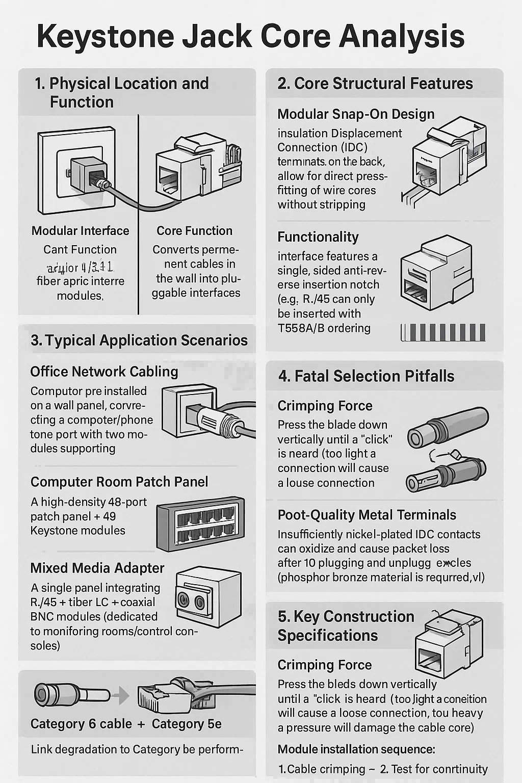
Keystone Jack Core Analysis
1. Physical Location and Function
Modular Interface Carrier: A square port embedded in a wall panel/patch panel, carrying RJ45, RJ11, or fiber optic interface modules, enabling connection between devices and network cables.
Core Function: Converts permanent cables in the wall into pluggable interfaces, preventing damage from repeated bending.
2. Core Structural Features
Modular Snap-On Design:
Insulation Displacement Connection (IDC) terminals on the back allow for direct press-fitting of wire cores without stripping.
Standardized front openings are compatible with all brands of modules (e.g., Category 5e/6/6A RJ45 modules).
Functionality:
The interface features a single-sided anti-reverse insertion notch (e.g., an RJ45 can only be inserted one way).
The punch-down area is color-coded with T568A/B to ensure standard ordering.
3. Typical Application Scenarios
Office Network Cabling: Keystone pre-installed on a wall panel, connecting a computer/phone (one port with two modules supporting data and voice). Computer Room Patch Panel: A high-density 48-port patch panel = 48 Keystone modules (easier to maintain than an all-in-one model).
Mixed Media Adapter: A single panel integrates RJ45 + fiber LC + coaxial BNC modules (dedicated to monitoring rooms/control consoles).
4. Fatal Selection Pitfalls
Bandwidth Mismatch: Category 6 cable + Category 5e Keystone → Link degradation to Category 5e performance.
Poor-Quality Metal Terminals: Insufficiently nickel-plated IDC contacts can oxidize and cause packet loss after 10 plugging and unplugging cycles (phosphor bronze material is required).
Fire Rating Blind Spot: Using PVC Keystone in a suspended ceiling (which does not meet flame retardancy standards) can release toxic smoke in the event of a fire.
5. Key Construction Specifications
Crimping Force: Press the blade down vertically until a "click" is heard (too light a connection will cause a loose connection; too heavy a pressure will damage the cable core).
Reserved Cable Length: Allow ≥15cm of cable inside the panel box to avoid strain on the terminals from repeated plugging and unplugging. Module installation sequence:
1. Cable crimping → 2. Test for continuity → 3. Snap the module into the panel (to prevent damage to the latches during rework).


Are you ready to
cooperate with PUXIN?
cooperate with PUXIN?
Contact us to find out how our products can transform your business and
take it to the next level.
Ningbo Puxin Electronic Technology Co., Ltd. is a professional supplier of electrical engineering and integrated wiring product research and development and manufacturing.
Quick Links
Products
Keep In Touch
-

No.43 of Xiaotuanpu Road, Guanhaiwei Town, Cixi Ningbo City, Zhejiang, China
-

-

8615924366333
-

Mobile web