What Cable Is Best for Patch Panels? Complete Guide
2026-04-13
Content
- 1 The Short Answer: Cat6 Is the Most Widely Preferred Cable for Patch Panels
- 2 Understanding How Cable Choice Affects Your Network Patch Panel Performance
- 3 Cable Categories Compared: Cat5e vs Cat6 vs Cat6A for Patch Panel Use
- 4 Shielded vs Unshielded Cable: Which Works Better with Patch Panels?
- 5 T568A vs T568B: Which Wiring Standard to Use at the Patch Panel
- 6 Patch Cord Selection: The Other Half of the Patch Panel Cable Equation
- 7 Fiber Optic Cable and Patch Panels: A Different Category Altogether
- 8 Common Mistakes When Choosing Cable for Network Patch Panels
- 9 How to Choose the Right Cable for Your Specific Patch Panel Scenario
- 10 Testing and Certifying Your Patch Panel Cable Installation
The Short Answer: Cat6 Is the Most Widely Preferred Cable for Patch Panels
When it comes to network patch panels, Cat6 unshielded twisted pair (UTP) cable is the most commonly recommended and widely deployed choice for most business and home network environments. It strikes the right balance between performance, cost, and future-proofing. That said, the best cable for your specific patch panel setup depends on your speed requirements, cable run lengths, interference conditions, and budget. Cat5e remains perfectly viable for gigabit networks on a tight budget, while Cat6A is the go-to for 10GbE installations or high-density data centers.
This guide walks through every major cable type used with patch panels, explains the technical differences that actually matter in real deployments, and helps you make a confident, informed decision without overcomplicating it.
Understanding How Cable Choice Affects Your Network Patch Panel Performance
A network patch panel is a passive piece of hardware — it does not amplify or regenerate signals. Every connection you make through it is only as good as the cable on either side. The cable you punch down into the back of your patch panel and the patch cord you plug into the front both contribute to signal quality, latency, and maximum throughput.
Key electrical properties that vary by cable category include:
- Attenuation — signal loss over distance. Higher category cables maintain stronger signals across longer runs.
- Crosstalk (NEXT and FEXT) — interference between adjacent wire pairs. Cat6 and Cat6A use tighter twists and physical separators to reduce this significantly.
- Bandwidth — measured in MHz, this determines how much data the cable can carry. Cat5e handles 100 MHz, Cat6 handles 250 MHz, and Cat6A reaches 500 MHz.
- Return loss — reflected signal energy that can degrade performance at high speeds.
Because a patch panel introduces additional connection points — punch-down terminations at the back and RJ45 ports at the front — using a cable category that matches or exceeds your panel's rated category is essential. Mixing a Cat6A patch panel with Cat5e horizontal runs, for instance, immediately limits your system to Cat5e performance regardless of what the panel itself is rated for.
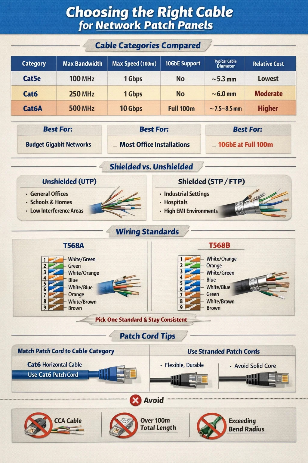
Cable Categories Compared: Cat5e vs Cat6 vs Cat6A for Patch Panel Use
The three categories you will encounter most often in structured cabling environments are Cat5e, Cat6, and Cat6A. Here is how they stack up against each other in a direct comparison:
| Category | Max Bandwidth | Max Speed (100m) | 10GbE Support | Typical Cable Diameter | Relative Cost |
|---|---|---|---|---|---|
| Cat5e | 100 MHz | 1 Gbps | No | ~5.3 mm | Lowest |
| Cat6 | 250 MHz | 1 Gbps | Up to 55m | ~6.0 mm | Moderate |
| Cat6A | 500 MHz | 10 Gbps | Full 100m | ~7.5–8.5 mm | Higher |
Cat5e: Still Relevant for Budget Gigabit Networks
Cat5e (Category 5 enhanced) was the dominant structured cabling standard through the 2000s and remains in active use today. It supports gigabit Ethernet (1000BASE-T) at full 100-meter runs and costs noticeably less per foot than Cat6 or Cat6A. For retrofitting older buildings or connecting low-demand endpoints like VoIP phones, security cameras, or basic workstations, Cat5e paired with a Cat5e-rated patch panel is completely adequate.
The limitation is future-proofing. Cat5e cannot reliably support 10 Gigabit Ethernet, and its crosstalk performance is lower than Cat6. If you are installing new cabling and expect to upgrade your network infrastructure in the next five to ten years, spending the small premium on Cat6 makes more sense.
Cat6: The Sweet Spot for Most Patch Panel Installations
Cat6 is the most commonly specified cable for new structured cabling projects that involve a network patch panel. The 250 MHz bandwidth doubles Cat5e's capacity, crosstalk performance is significantly better due to tighter pair twists and an internal plastic spline (separator) found in many Cat6 constructions, and it supports 10 Gbps speeds over shorter runs of up to 55 meters.
For a typical office environment where horizontal runs average 20–40 meters, Cat6 comfortably handles 10GbE if your switch infrastructure supports it. The price premium over Cat5e is typically 10–20% per foot — a small difference that pays off over the life of the installation. Cat6 patch panels are widely available in 24-port and 48-port configurations and are compatible with all standard 110-style punch-down tools.
Cat6A: The Right Choice for 10GbE at Full Distance
Cat6A (Augmented Category 6) is the current recommended standard for any installation where 10 Gigabit Ethernet must be maintained across a full 100-meter horizontal run. It operates at 500 MHz bandwidth, uses either a shielded (F/UTP or S/FTP) or unshielded construction with much thicker insulation, and meets the alien crosstalk requirements that Cat6 cannot.
The trade-off is physical size and weight. Cat6A cables are considerably thicker — typically 7.5 to 8.5 mm in diameter versus 6 mm for Cat6 — which means tighter conduit fill calculations, heavier cable trays, and more demanding bend radius management. Cat6A patch panels are also larger and more expensive. However, in data centers, healthcare facilities, or any environment deploying 10GbE to the desktop or edge switches, Cat6A is the correct choice and is explicitly specified in TIA-568-C.2 for 10GBASE-T applications.
Shielded vs Unshielded Cable: Which Works Better with Patch Panels?
One decision that confuses many network installers is whether to use shielded (STP/FTP/S/FTP) or unshielded (UTP) cable for patch panel runs. The answer depends heavily on your environment.
When Unshielded (UTP) Cable Is the Right Call
The vast majority of network patch panel installations in commercial offices, schools, retail environments, and homes use UTP cable. It is easier to terminate, more flexible, lighter, and cheaper than shielded alternatives. As long as the cable is kept away from high-interference sources — such as fluorescent light ballasts, large motors, or parallel power cable runs exceeding 2 meters — UTP performs excellently.
TIA-568 standards allow UTP cable to run within 5 cm of unshielded power cables and within 12 cm of fluorescent lighting fixtures. Keep those clearances and UTP will give you clean, reliable performance without the grounding complexity of shielded systems.
When Shielded Cable Becomes Necessary
Shielded cable is the correct choice in environments with significant electromagnetic interference (EMI) sources, including:
- Manufacturing floors with heavy electrical machinery
- Hospitals with MRI suites or high-powered imaging equipment
- Broadcast studios with radio frequency equipment
- Industrial environments where cable must run near VFDs (variable frequency drives)
- Outdoor or semi-outdoor installations subject to lightning exposure
When you use shielded cable, your patch panel must also be shielded and properly grounded. A shielded cable terminated on an ungrounded or unshielded patch panel can actually perform worse than UTP because the unconnected shield acts as an antenna, collecting interference rather than rejecting it. The entire shielded channel — cable, patch panel, keystone jacks, and patch cords — must be grounded at one point to be effective.
T568A vs T568B: Which Wiring Standard to Use at the Patch Panel
Both T568A and T568B are valid TIA/EIA wiring standards for terminating Ethernet cables at patch panel punch-down ports. The technical performance difference between the two is negligible — both support the same speeds and distances. The important rule is consistency: use the same standard throughout the entire installation.
T568B is more common in North American commercial installations and is used by the majority of pre-made patch cords sold in the US market. T568A is preferred in government installations (it is specified by the US government's TIA-568-C standard for federal buildings) and is common in Europe and Australia.
If you are extending or adding to an existing installation, always match the standard already in use. Mixing T568A and T568B within the same end-to-end channel creates a crossover, not a straight-through connection, which will prevent your link from coming up on most switches.
| Pin | T568A Color | T568B Color | Pair |
|---|---|---|---|
| 1 | White/Green | White/Orange | Pair 3 / Pair 2 |
| 2 | Green | Orange | Pair 3 / Pair 2 |
| 3 | White/Orange | White/Green | Pair 2 / Pair 3 |
| 4 | Blue | Blue | Pair 1 |
| 5 | White/Blue | White/Blue | Pair 1 |
| 6 | Orange | Green | Pair 2 / Pair 3 |
| 7 | White/Brown | White/Brown | Pair 4 |
| 8 | Brown | Brown | Pair 4 |
Patch Cord Selection: The Other Half of the Patch Panel Cable Equation
Most people focus entirely on the horizontal cable run when thinking about what cable to use with a patch panel, but the patch cord connecting the panel port to your switch is equally important. A patch cord that is a lower category than your horizontal cable creates a bottleneck at the connection point.
Match Patch Cord Category to Your Horizontal Cable
If you have run Cat6 to your patch panel, use Cat6 patch cords on the front. Using Cat5e patch cords on a Cat6 panel and Cat6 horizontal cable limits the channel to Cat5e performance. The same applies to Cat6A — always use Cat6A-rated patch cords with Cat6A patch panels and horizontal cabling.
Standard patch cord lengths for connecting patch panels to switches are typically 0.5m, 1m, 2m, or 3m. Shorter cords reduce signal loss and keep your rack tidy. Avoid buying bargain patch cords from unverified suppliers — poor-quality patch cords with loose pair twists or substandard connectors are one of the most common causes of intermittent link failures and reduced throughput in otherwise well-built structured cabling systems.
Stranded vs Solid Conductor Patch Cords
Patch cords use stranded conductors (multiple thin wires wound together) rather than solid conductors. Stranded cable is more flexible and resistant to physical fatigue from repeated bending and movement, making it ideal for the short, frequently-handled runs between patch panel and switch. Solid conductor cable — used for horizontal runs — is stiffer and will crack internally if flexed repeatedly.
Never use solid conductor cable as a patch cord. It will work initially, but the internal conductors will fatigue and fail after repeated plug insertions and cable movement.
Fiber Optic Cable and Patch Panels: A Different Category Altogether
Not all patch panels use copper Ethernet cable. Fiber optic patch panels — also called fiber distribution panels or fiber enclosures — are used for backbone cabling between equipment rooms, inter-building connections, and high-density data center interconnects. They serve a different function than copper patch panels and require completely different cable management practices.
Multimode vs Single-Mode Fiber at the Patch Panel
Fiber patch panels accept either multimode or single-mode fiber, and these cannot be interchanged. The choice depends on your transmission distance and application:
- OM3 multimode fiber supports 10GbE up to 300 meters and 40GbE up to 100 meters. It uses a 50-micron core and is common in campus and data center backbone applications.
- OM4 multimode fiber extends 10GbE to 550 meters and 100GbE to 150 meters. It is the preferred multimode standard for new data center installations.
- OS2 single-mode fiber supports transmission over distances of up to 10 km and beyond, making it essential for inter-building or campus-wide runs.
Fiber patch panels are passive devices that provide organized termination points for fiber runs. The actual fiber patch cords connecting equipment to the panel must use matching connector types (LC, SC, MPO/MTP) and matching fiber types. Connecting a multimode patch cord to a single-mode trunk fiber results in severe insertion loss and a non-functional link.
Common Mistakes When Choosing Cable for Network Patch Panels
Even experienced network installers make avoidable errors when selecting and installing cable for patch panel systems. These are the mistakes that show up most frequently in real-world troubleshooting:
Using CCA (Copper-Clad Aluminum) Cable
CCA cable — which uses aluminum conductors coated with a thin copper layer — is sold at dramatically lower prices than genuine copper cable, and it is frequently mislabeled as standard Ethernet cable online. CCA cable should never be used in patch panel installations. Aluminum has higher electrical resistance than copper, it corrodes faster at termination points, and it fails to meet TIA-568 or ISO/IEC 11801 standards. Many network failures traced back to poor link stability, excessive packet loss, or PoE (Power over Ethernet) devices not powering on reliably have turned out to be caused by CCA cable. Purchase cable only from reputable suppliers who can provide ETL or UL verification of pure copper conductors.
Exceeding the 100-Meter Channel Length
The TIA-568 standard specifies a maximum permanent link (horizontal run) of 90 meters, with the remaining 10 meters allocated to patch cords at each end, giving a total channel length of 100 meters. Many installers treat 100 meters as the horizontal run limit and then add patch cords on top, pushing the total channel past specification. A 95-meter horizontal run plus two 3-meter patch cords totals 101 meters — technically out of spec and potentially unreliable at gigabit speeds.
Mismatching Cable Category and Patch Panel Rating
Installing Cat6A cable on a Cat6-rated patch panel prevents you from achieving a certified Cat6A channel. The panel is the lowest-rated component in the link, and its performance characteristics set the ceiling for the entire run. Always match or exceed the cable category when selecting a patch panel. Using a Cat6A panel with Cat6 cable is acceptable — the panel is over-specified, which wastes money but does not hurt performance. The reverse is not acceptable.
Ignoring Bend Radius During Installation
Ethernet cable has a minimum bend radius that must be respected during installation. For Cat6 UTP, the minimum bend radius is typically four times the cable's outside diameter, or approximately 24 mm. Cat6A requires a larger bend radius due to its thicker construction. Tight bends deform the pair twists inside the cable, increasing crosstalk and degrading signal quality — sometimes enough to prevent certification testing from passing.
How to Choose the Right Cable for Your Specific Patch Panel Scenario
Rather than applying a single blanket recommendation, here is a practical decision guide based on common deployment scenarios:
- Small office or home network with up to 1 Gbps switching: Cat5e UTP with a Cat5e patch panel. Cost-effective, fully sufficient, and easy to terminate. No need to upgrade unless you plan to move to 10GbE switches.
- New commercial office installation expected to last 10+ years: Cat6 UTP with a Cat6 patch panel. Provides headroom for 10GbE over short runs and delivers superior noise performance versus Cat5e.
- Data center or high-density environment with 10GbE to the rack: Cat6A UTP (or F/UTP if EMI is a concern) with a Cat6A patch panel. This is the only copper option that supports 10GbE at full 100-meter runs.
- Inter-building or campus backbone links: OS2 single-mode fiber with LC connectors and a fiber patch panel. Copper Ethernet is not suitable for runs beyond 100 meters.
- Industrial environment with heavy electrical machinery: Cat6A F/UTP or S/FTP shielded cable with a grounded, shielded patch panel. Proper grounding at the panel is mandatory.
- Healthcare or education campus with mixed PoE and data requirements: Cat6A UTP, which handles the higher power delivery demands of PoE++ (90W IEEE 802.3bt) with lower heat buildup than Cat6 in bundled cable runs.
Testing and Certifying Your Patch Panel Cable Installation
Selecting the right cable category is only half the job. A Cat6 cable terminated incorrectly — with excessive pair untwist at the punch-down, a sharp bend near the panel, or a mismatched wiring standard — will fail to meet Cat6 performance levels even though the right cable was used. Professional structured cabling installations are verified with a cable certification tester, not just a basic continuity tester.
Cable certification testers from manufacturers like Fluke Networks (DSX-8000), IDEAL Networks, or Softing perform measurements including insertion loss, NEXT, FEXT, return loss, and propagation delay across the full frequency range of the cable category. A Cat6 channel certification requires passing all parameters up to 250 MHz; Cat6A requires 500 MHz. A passing certification report is the only reliable confirmation that your cable and patch panel combination will perform as specified.
For smaller DIY installations, a basic wire mapping tester confirms correct pin connections and identifies split pairs, opens, and shorts — the most common punch-down errors. While this does not certify performance, it catches wiring mistakes before equipment is connected.


Are you ready to
cooperate with PUXIN?
cooperate with PUXIN?
Contact us to find out how our products can transform your business and
take it to the next level.
Ningbo Puxin Electronic Technology Co., Ltd. is a professional supplier of electrical engineering and integrated wiring product research and development and manufacturing.
Quick Links
Products
Keep In Touch
-

No.43 of Xiaotuanpu Road, Guanhaiwei Town, Cixi Ningbo City, Zhejiang, China
-

-

8615924366333
-

Mobile web